ENSP网络综合实验
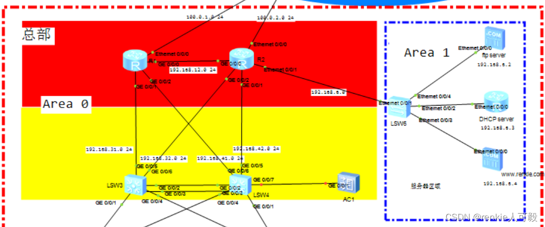
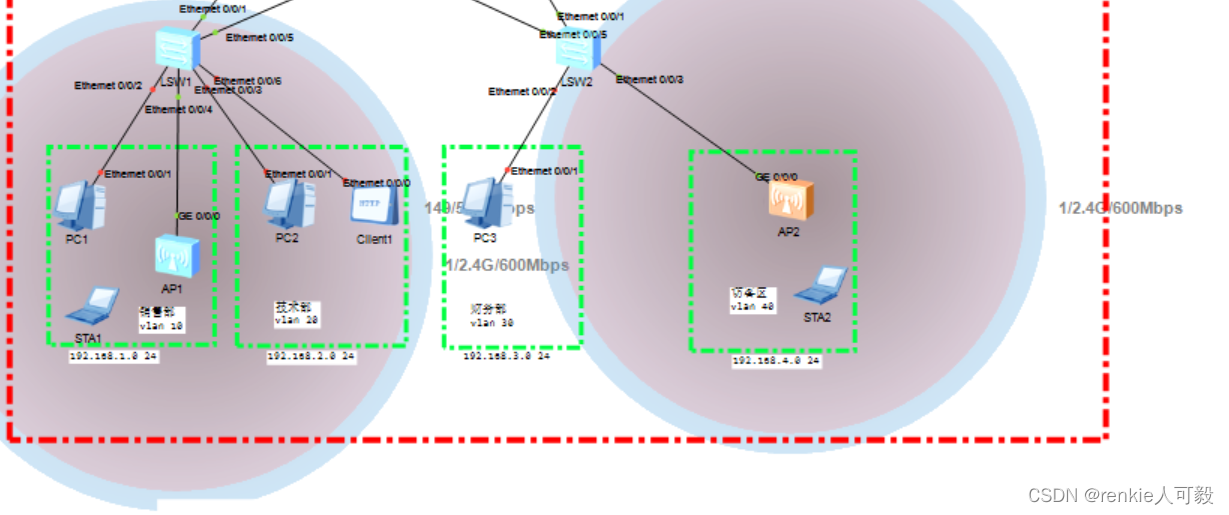
拓扑图总公司一共有三个部门:销售部、技术部、财务部,临设访客区域。分公司这里简化为只有一个技术部门配置需求1.销售部、技术部、财务部,访客区域分别划分到VLAN10-VLAN402.销售部可通过有线、无线访问网络,访客区域提供访客无线服务。3.配置步骤1.销售部、技术部、财务部,访客区域分别划分到VLAN10-VLAN40分别在LSW1和LSW2基于接口划分VLAN,终端不必配置ip地址,后面配置
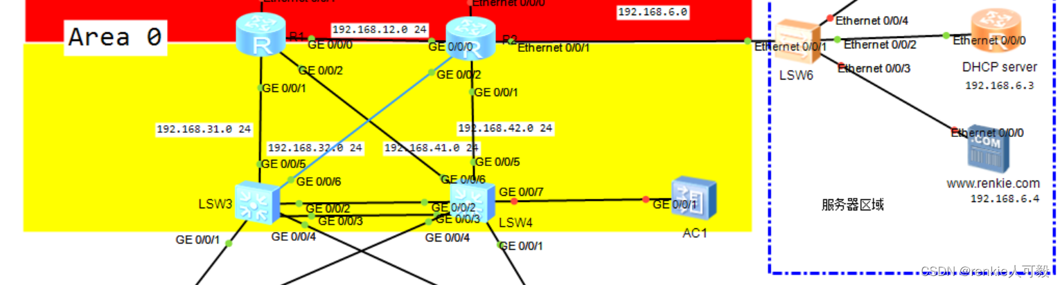
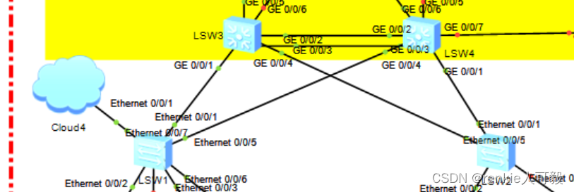
拓扑图 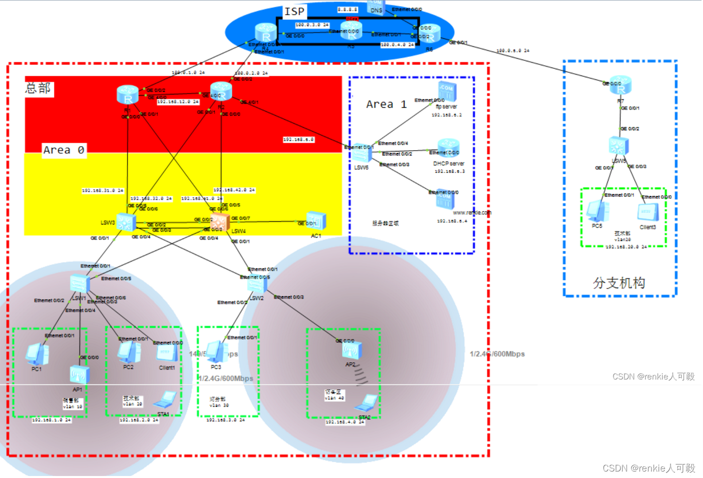
总公司一共有三个部门:销售部、技术部、财务部,临设访客区域。分公司这里简化为只有一个技术部门
配置步骤
1.销售部、技术部、财务部,访客区域分别划分到VLAN10-VLAN40
2.在三层交换机LSW3、LSW4上配置VLAN10-VLAN20的网关
3.配置链路聚合
4.配置MSTP+VRRP
5.配置路由协议
6.配置DHCP协议
7.配置WLAN
8.配置NAT
9.ISP配置
10.分支机构配置
11.配置NAT server
12.配置服务器:模拟DNS解析访问WEB服务器以及FTP文件服务器
配置DNS服务器
配置WEB服务器
配置FTP服务器
模拟通过DNS解析访问web服务器
13.NAT DNS-Map
14.部门网络权限配置
15.配置IPSec VPN
16.通过SSH远程管理设备
1.销售部、技术部、财务部,访客区域分别划分到VLAN10-VLAN40
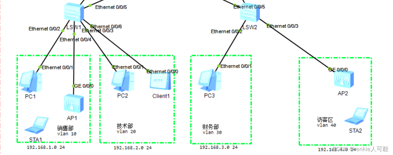
分别在LSW1和LSW2基于接口划分VLAN,终端不必配置ip地址,后面配置DHCP自动获取 。
以LSW1为例:
interface Ethernet0/0/2
 port link-type access
 port default vlan 10

interface Ethernet0/0/3
 port link-type access
 port default vlan 20

interface Ethernet0/0/6
 port link-type access
 port default vlan 20
注意:连接AP的接口,我们后面在WLAN在进行配置。
2.在三层交换机LSW3、LSW4上配置VLAN10-VLAN20的网关
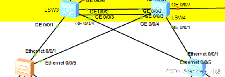
首先二层交换机与三层交换机的链路类型采用Trunk,允许VLAN10~VLAN40通过,在LSW3、LSW4上创建vlan10 -vlan20的vlanif接口。(这里的链路、设备做了冗余。)
以LSW1、LSW3为例:
#LSW1:
vlan batch 10 20 30 40
interface Ethernet0/0/1
 port link-type trunk
 port trunk allow-pass vlan 10 20 30 40

interface Ethernet0/0/5
 port link-type trunk
 port trunk allow-pass vlan 10 20 30 40
*******************************************************************************************
#LSW3:
vlan batch 10 20 30 to 32 40
interface Vlanif10
 ip address 192.168.1.1 255.255.255.0
interface Vlanif20
 ip address 192.168.2.1 255.255.255.0
interface Vlanif30
 ip address 192.168.3.1 255.255.255.0
interface Vlanif40
 ip address 192.168.2.1 255.255.255.0
interface GigabitEthernet0/0/1
 port link-type trunk
 port trunk allow-pass vlan 10 20 30 40
interface GigabitEthernet0/0/4
 port link-type trunk
 port trunk allow-pass vlan 10 20 30 40
3.配置链路聚合
以LSW3为例:
interface Eth-Trunk1
 port link-type trunk
 port trunk allow-pass vlan 10 20 30 40
 mode lacp-static
trunkport GigabitEthernet 0/0/2 0/0/3
4.配置MSTP+VRRP
在LSW3和LSW4分别配置实例,将VLAN10和VLAN20划分进实例1,将VLAN20和VLAN30划分进实例2,LSW3为实例1的主根,LSW4为实例2的主根。
在LSW1、LSW2、LSW3、LSW4配置:
stp mode mstp
stp region-configuration
 instance 1 vlan 10 20
 instance 2 vlan 30 40
 active region-configuration
在LSW3上配置和LSW4上配置:
LSW3:
stp instance 1 root primary
stp instance 2 root secondary
*******************************************************************************************
LSW4:
stp instance 2 root primary
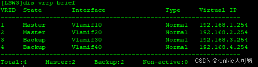
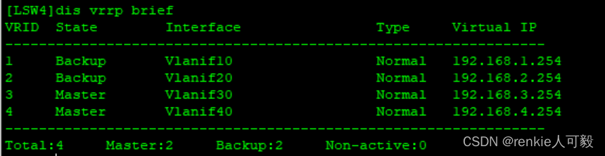
stp instance 1 root secondary配置VRRP,vlan10、vlan20的master路由器为LSW3,vlan30、vlan40的主master路由器为LSW4,且配置抢占延时为60s。
LSW3:
interface Vlanif10
 ip address 192.168.1.1 255.255.255.0
 vrrp vrid 1 virtual-ip 192.168.1.254
 vrrp vrid 1 priority 120
 vrrp vrid 1 preempt-mode timer delay 60

interface Vlanif20
 ip address 192.168.2.1 255.255.255.0
 vrrp vrid 2 virtual-ip 192.168.2.254
 vrrp vrid 2 priority 120
 vrrp vrid 2 preempt-mode timer delay 60

interface Vlanif30
 ip address 192.168.3.1 255.255.255.0
 vrrp vrid 3 virtual-ip 192.168.3.254

interface Vlanif40
 ip address 192.168.4.1 255.255.255.0
 vrrp vrid 4 virtual-ip 192.168.4.254
*****************************************************************************************
LSW4:
interface Vlanif10
 ip address 192.168.1.2 255.255.255.0
 vrrp vrid 1 virtual-ip 192.168.1.254

interface Vlanif20
 ip address 192.168.2.2 255.255.255.0
 vrrp vrid 2 virtual-ip 192.168.2.254

interface Vlanif30
 ip address 192.168.3.2 255.255.255.0
 vrrp vrid 3 virtual-ip 192.168.3.254
 vrrp vrid 3 priority 120
 vrrp vrid 3 preempt-mode timer delay 60

interface Vlanif40
 ip address 192.168.4.2 255.255.255.0
 vrrp vrid 4 virtual-ip 192.168.4.254
 vrrp vrid 4 priority 120
 vrrp vrid 4 preempt-mode timer delay 60
分别在LSW3/LSW4查看VRRP状态:
 将交换机连接路由器和终端的接口配置为边缘接口,以LSW1为例:
port-group group-member Ethernet 0/0/2 Ethernet 0/0/4 Ethernet 0/0/3 Ethernet 0/0/6
stp edged-port enable
port-group group-member 用于批量配置接口
5.配置路由协议
 由于模拟器不支持直接在三层接口配置ip地址,所以采用vlanif接口来配置。以LSW3和R1互联为例:
LSW3:
vlan batch 31 32
interface Vlanif31
ip address 192.168.31.1 255.255.255.252
#
interface Vlanif32
ip address 192.168.32.1 255.255.255.252
#
interface GigabitEthernet0/0/5
port link-type trunk
port trunk pvid vlan 31
port trunk allow-pass vlan 31
#
interface GigabitEthernet0/0/6
port link-type trunk
port trunk pvid vlan 32
port trunk allow-pass vlan 32
*******************************************************************************************
R1:
interface GigabitEthernet0/0/1
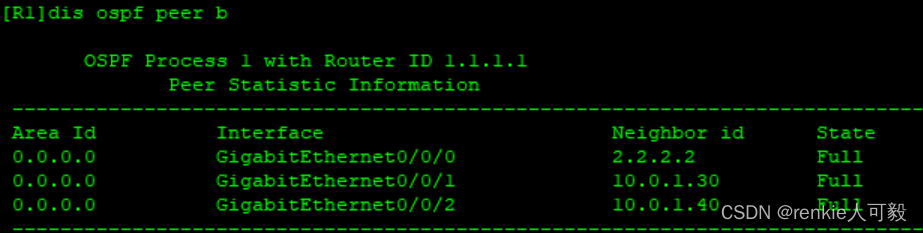
ip address 192.168.31.2 255.255.255.252在三层交换机和路由器上配置ospf协议,将其互联网段宣告进ospf area0中,以R1为例:
ospf 1 router-id 1.1.1.1
 area 0.0.0.0
  network 192.168.31.2 0.0.0.0
  network 192.168.41.2 0.0.0.0
  network 192.168.12.1 0.0.0.0
  network 1.1.1.1 0.0.0.0
  network 192.168.13.1 0.0.0.0
查看ospf邻居建立情况:
将三层交换机下连直连网段引入ospf中,并通过路由策略,过滤不必要路由。
acl number 2000
 rule 5 permit source 192.168.0.0 0.0.255.255
route-policy im permit node 10
 if-match acl 2000
ospf 1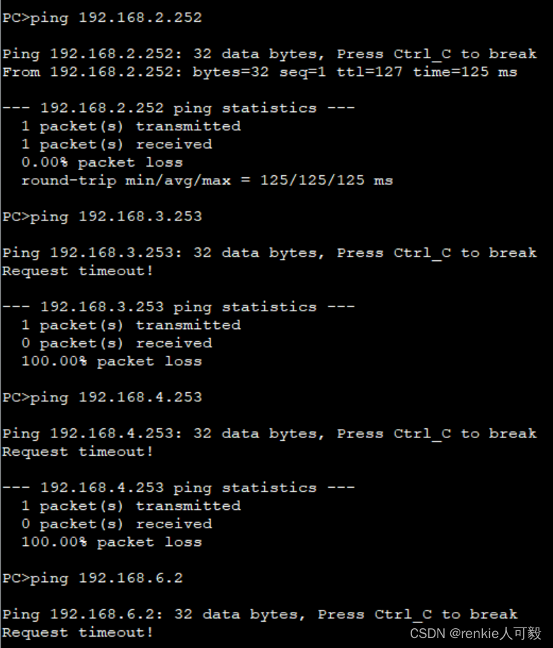
import-route direct route-policy im将R2连接的服务器区域网络宣告进area1 中,并把区域1配置totally stub区域,减小区域1的路由规模,防止区域0引起的路由震荡问题。
 area 0.0.0.1
  network 192.168.6.0 0.0.0.255
  stub no-summary
在R1和R2上配置静态缺省出口路由,并在ospf中下发缺省路由。
至此全网互通。
6.配置DHCP协议
这里我们用路由器模拟DHCP服务器,由于服务器与待分配的ip不在同一网段,所以需要配置DHCP Relay。
DHCP Server配置 :
dhcp enable

ip pool vlan10
 gateway-list 192.168.1.254
 network 192.168.1.0 mask 255.255.255.0
 dns-list 8.8.8.8

ip pool vlan20
 gateway-list 192.168.2.254
 network 192.168.2.0 mask 255.255.255.0
 dns-list 8.8.8.8

ip pool vlan30
 gateway-list 192.168.3.254
 network 192.168.3.0 mask 255.255.255.0
 dns-list 8.8.8.8

ip pool vlan40
 gateway-list 192.168.4.254
 network 192.168.4.0 mask 255.255.255.0
 dns-list 8.8.8.8

interface Ethernet0/0/0
 ip address 192.168.6.3 255.255.255.0
 dhcp select global
ip route-static 0.0.0.0 0.0.0.0 192.168.6.1 #由与DHCP server用的是路由器,没有到area 0的路由,故写一条静态默认路由到R2。
在LSW3和LSW3上配置DHCP Relay,以LSW3为例:
interface Vlanif10
 dhcp select relay
 dhcp relay server-ip 192.168.6.3
interface Vlanif20
 dhcp select relay
 dhcp relay server-ip 192.168.6.3
interface Vlanif30
 dhcp select relay
 dhcp relay server-ip 192.168.6.3
interface Vlanif40
 dhcp select relay
 dhcp relay server-ip 192.168.6.3
选择DHCP,点击应用,查看配置信息,成功获取到ip地址。
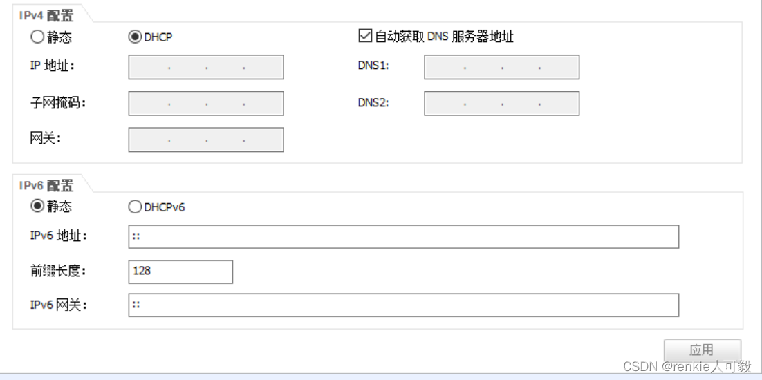
7.配置WLAN
我们采用二层旁挂式直接转发组网的方式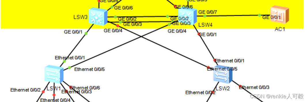
首先我们在AC上创建一个管理VLAN100,用来管理AP:给AP分配地址。
vlan batch 100
interface Vlanif100
 ip address 192.168.100.254 255.255.255.0
在交换机与交换机、交换机与AC的互联链路允许VLAN100通过。以AC为例:
vlan batch 100
interface GigabitEthernet0/0/1
 port link-type trunk
 port trunk allow-pass vlan 100
在AC上创建地址池,用于给AP分配ip地址,并在接口下配置全局应用。
dhcp enable
ip pool ap
 gateway-list 192.168.100.254
 network 192.168.100.0 mask 255.255.255.0
int vlanif 100
 dhcp select global
将交换机连接AP的接口链路类型配置为trunk,允许vlan100以及STA业务流量vlan20通过。
interface Ethernet0/0/4
 port link-type trunk
 port trunk pvid vlan 100
 port trunk allow-pass vlan 20 100
AP通过DHCP获取到了IP地址
![]()
![]()
在AC上创建AP组
# 创建AP组,用于将相同配置的AP都加入同一AP组中
[AC] wlan
[AC-wlan-view] ap-group name ap-group1
[AC-wlan-ap-group-ap-group1] quit
[AC-wlan-view] ap-group name ap-group2
创建域管理模板,并配置AC的国家码。
AC-wlan-view] regulatory-domain-profile name default
[AC-wlan-regulate-domain-default] country-code cn
[AC-wlan-regulate-domain-default] quit
[AC-wlan-view] ap-group name ap-group1
[AC-wlan-ap-group-ap-group1] regulatory-domain-profile default

Warning: Modifying the country code will clear channel, power and antenna gain configurations of the radio and reset the AP. Continue?[Y/N]:y

[AC-wlan-view] ap-group name ap-group2
[AC-wlan-ap-group-ap-group2] regulatory-domain-profile default

Warning: Modifying the country code will clear channel, power and antenna gain configurations of the radio and reset the AP. Continue?[Y/N]:y
配置AC的源接口。
[AC] capwap source interface vlanif 100
在AC上离线导入AP。
[AC] wlan
[AC-wlan-view] ap auth-mode mac-auth
[AC-wlan-view] ap-id 0 ap-mac 00e0-fc0f-6500
[AC-wlan-ap-0] ap-name area_1
Warning: This operation may cause AP reset. Continue? [Y/N]:y
[AC-wlan-ap-0] ap-group ap-group1
Warning: This operation may cause AP reset. If the country code changes, it will clear channel, power and antenna gain configurations of the radio, Whether to continue? [Y/N]:y
[AC-wlan-view] ap-id 1 ap-mac 00e0-fce3-4190
[AC-wlan-ap-0] ap-name area_2
Warning: This operation may cause AP reset. Continue? [Y/N]:y
[AC-wlan-ap-0] ap-group ap-group2
Warning: This operation may cause AP reset. If the country code changes, it will clear channel, power and antenna gain configurations of the radio, Whether to continue? [Y/N]:y
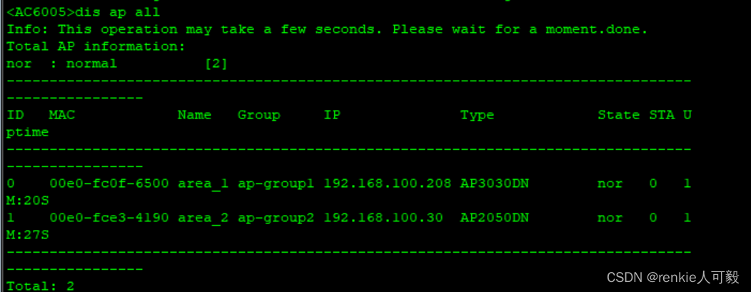
注:ap-mac可通过在AP上执行'dis interface Vlanif 1'查看,和本实验的mac地址是不一样的。 查看AP上线
创建名为“wlan-net”的安全模板,并配置安全策略。
[AC-wlan-view] security-profile name wlan-net
[AC-wlan-sec-prof-wlan-net] security wpa-wpa2 psk pass-phrase a1234567 aes
[AC-wlan-sec-prof-wlan-net] quit
创建名为“JiShu”的SSID模板,并配置SSID名称为“JiShu”,名为“FangKe”的SSID模板,并配置SSID名称为“FangKe”。
[AC-wlan-view] ssid-profile name JiShu
[AC-wlan-ssid-prof-wlan-net] ssid JiShu
[AC-wlan-ssid-prof-wlan-net] quit
[AC-wlan-view] ssid-profile name FangKe
[AC-wlan-ssid-prof-wlan-net] ssid FangKe分别创建名为“JiShu”、“FangKe”的VAP模板,配置业务数据转发模式、业务VLAN,并且引用安全模板和SSID模板。
[AC-wlan-view] vap-profile name JiShu
[AC-wlan-vap-prof-wlan-net] forward-mode direct-forward
[AC-wlan-vap-prof-wlan-net] service-vlan vlan-id 20
[AC-wlan-vap-prof-wlan-net] security-profile wlan-net
[AC-wlan-vap-prof-wlan-net] ssid-profile JiShu
[AC-wlan-vap-prof-wlan-net] quit

[AC-wlan-view] vap-profile name FangKe
[AC-wlan-vap-prof-wlan-net] forward-mode direct-forward
[AC-wlan-vap-prof-wlan-net] service-vlan vlan-id 40
[AC-wlan-vap-prof-wlan-net] security-profile wlan-net
[AC-wlan-vap-prof-wlan-net] ssid-profile FangKe
[AC-wlan-vap-prof-wlan-net] quit
配置AP组引用VAP模板,AP上射频0使用VAP模板“wlan-net”的配置。
[AC-wlan-view] ap-group name ap-group1
[AC-wlan-ap-group-ap-group1] vap-profile JiShu wlan 1 radio 0
[AC-wlan-ap-group-ap-group1] vap-profile JiShu wlan 1 radio 1
[AC-wlan-ap-group-ap-group1] quit
[AC-wlan-view] ap-group name ap-group2
[AC-wlan-ap-group-ap-group1] vap-profile FangKe wlan 1 radio 0
[AC-wlan-ap-group-ap-group1] vap-profile FangKe wlan 1 radio 1
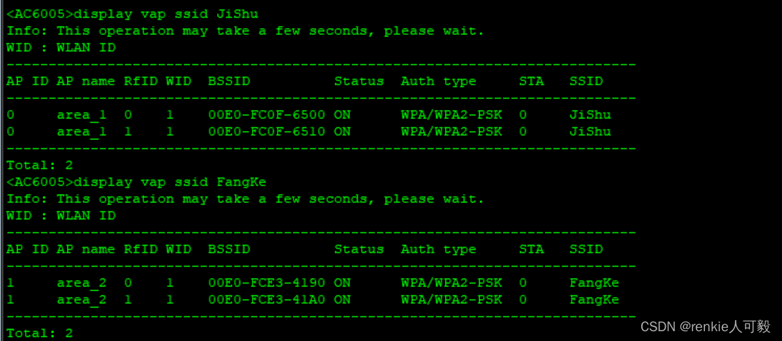
[AC-wlan-ap-group-ap-group1] quit查看VAP模板信息
WLAN业务配置会自动下发给AP,配置完成后,通过执行命令查看如下信息,当“Status”项显示为“ON”时,表示AP对应的射频上的VAP已创建成功。
此时AP附近出现了无线信号圈
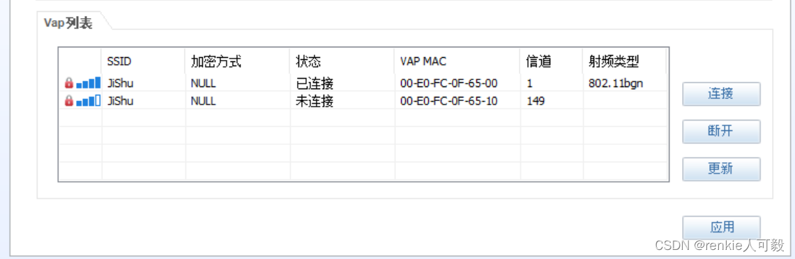
结果验证 :
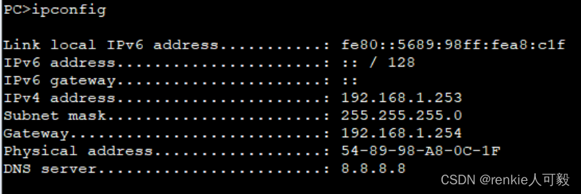
STA通过DHCP获取地址
1.将STA获取ip地址的方式选为DHCP,点击应用。注意,在没有点击连接的时候,STA是无法自动获取到ip地址的。
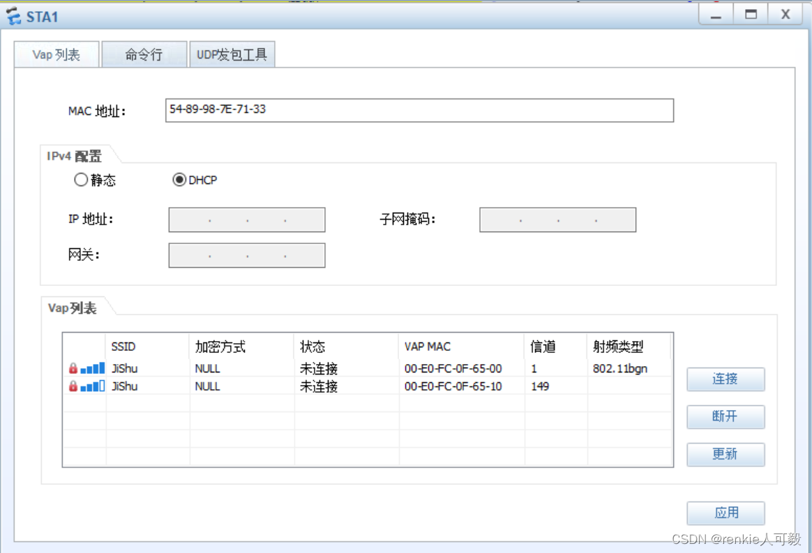
2.双击vap列表的wlan,弹出输入密码界面,输入前面配置的密码:a1234567 。可以看到正在获取ip...到已连接的阶段。
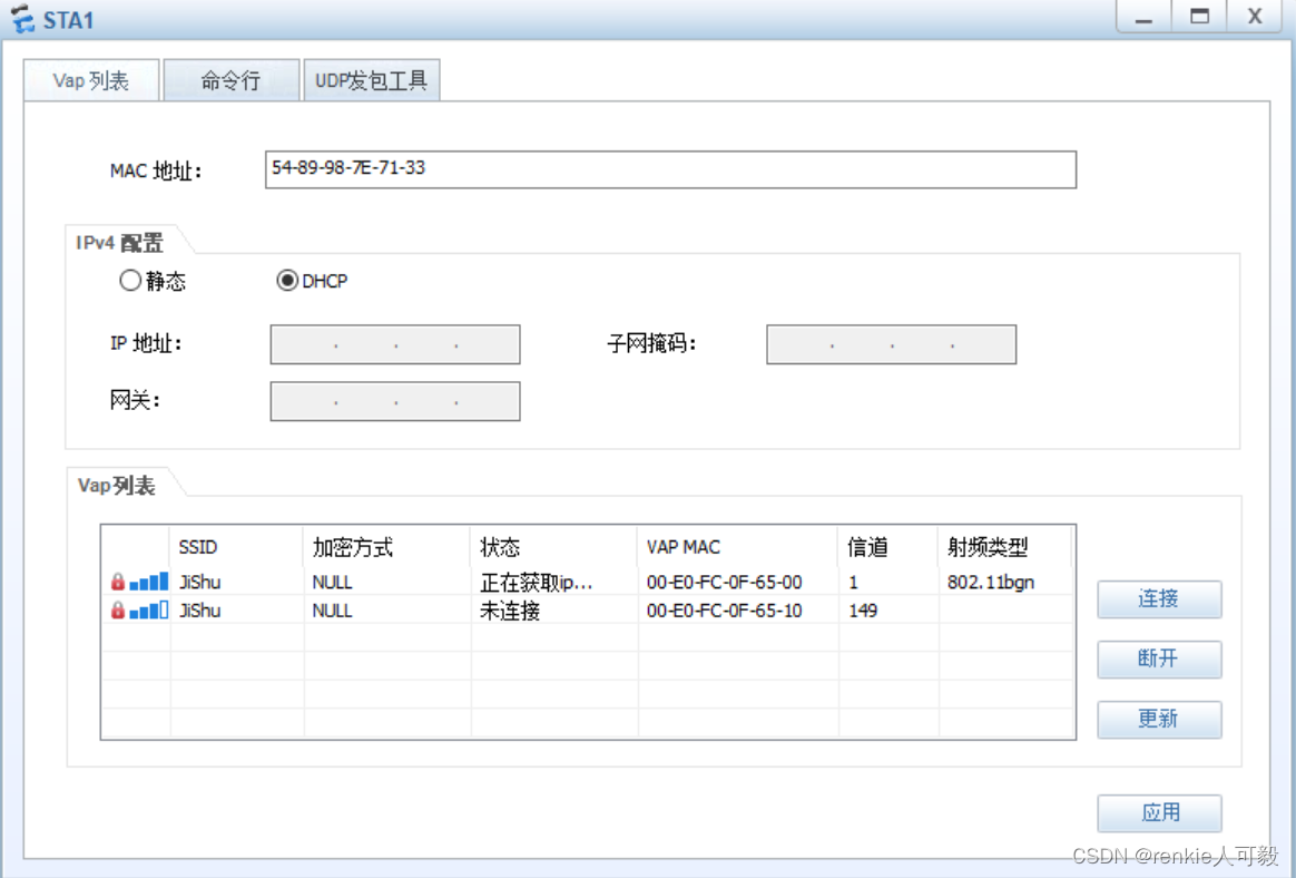
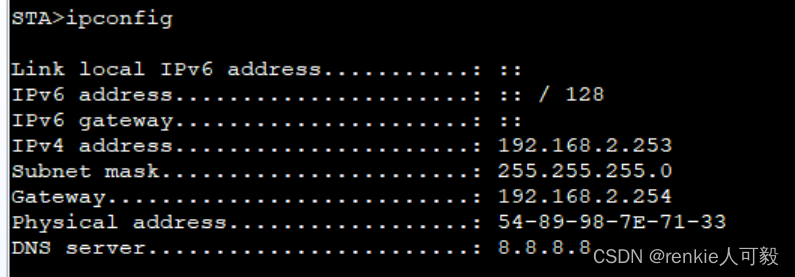
 3.通过ipconfig命令可以看到STA已获取ip地址
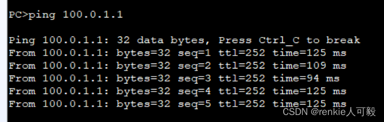
此时测试PC1访问位于公网的R4的e0/0/0地址,可以访问。
8.配置NAT
在R1、R2上配置easy-ip,模拟器上只能用AR系列的路由器,配置如下:
acl 2000
interface GigabitEthernet0/0/2
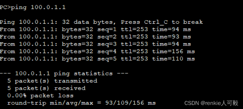
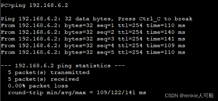
nat outbound 2000PC1能ping通外网
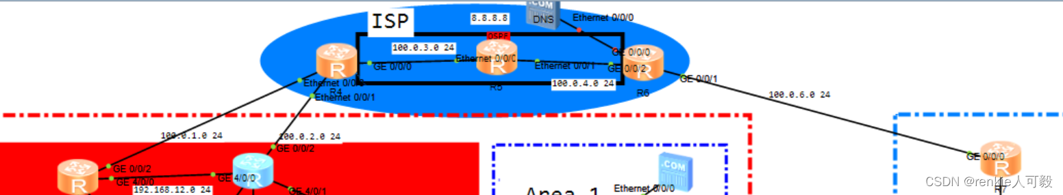
9.ISP配置
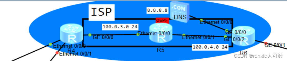
配置IGP协议:OSPF,此步骤略。
R4与R6建立BGP邻居关系,为了防止路由黑洞,我们这里采用将R4和R6边缘接口宣告进ospf。
R4
bgp 100
 peer 6.6.6.6 as-number 100
 peer 6.6.6.6 connect-interface LoopBack0
ospf 1
 area 0.0.0.0
  network 100.0.1.0 0.0.0.255
  network 100.0.2.0 0.0.0.255
*******************************************************************************************
R6
bgp 100
 peer 4.4.4.4 as-number 100
 peer 4.4.4.4 connect-interface LoopBack0
ospf 1
 are 0
  network 100.0.6.0 0.0.0.255
10.分支机构配置
分支机构通过PPPoE拨号获取出口公网地址
R6配置:
ip pool ppoe
 network 100.0.6.0 mask 255.255.255.0
 dns-list 8.8.8.8
interface Virtual-Template1
 remote address pool ppoe
 ip address unnumbered interface GigabitEthernet0/0/1 #用g0/0/1的ip地址作为Virtual-Template1地址
aaa
 local-user huawei password cipher huawei@123
 local-user huawei service-type ppp
interface GigabitEthernet0/0/1
pppoe-server bind Virtual-Template 1
R7配置:
interface Dialer1
 link-protocol ppp
 ppp chap user huawei
 ppp chap password cipher huawei@123
 ip address ppp-negotiate
 dialer user huawei
 dialer bundle 1
 dialer-group 1
interface GigabitEthernet0/0/0
 pppoe-client dial-bundle-number 1
R7获取到了地址
NAT配置 ,采用easy-ip。
acl number 2000
 rule 5 permit source 192.168.20.0 0.0.0.255
ip route-static 0.0.0.0 0.0.0.0 Dialer1
interface Dialer1
 nat outbound 2000
11.配置NAT server
NAT server配置,以R1为例:
nat server protocol tcp global current-interface www inside 192.168.6.4 www
##
AR路由器在配置NAT映射时,公网IP不能与接口IP地址相同,否则会提示冲突,导致配置不上去。如果只有一个公网IP时,可以做端口映射,公网IP使用current-interface参考代替,如下:
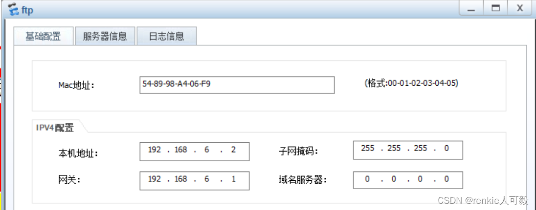
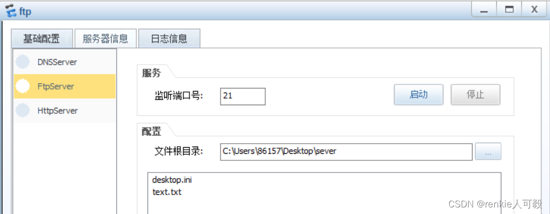
nat server protocol tcp global current-interface 80 inside xxxxx 80 12.配置服务器:模拟DNS解析访问WEB服务器以及FTP文件服务器
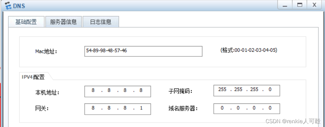
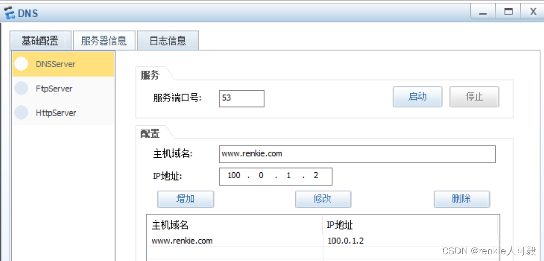
配置DNS服务器
配置WEB服务器
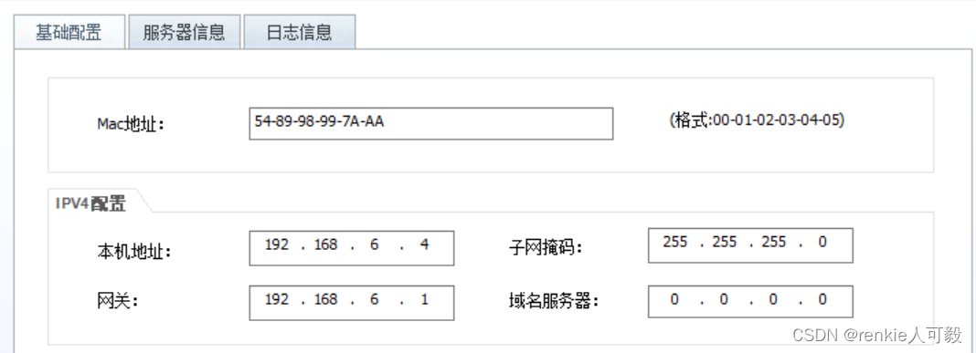
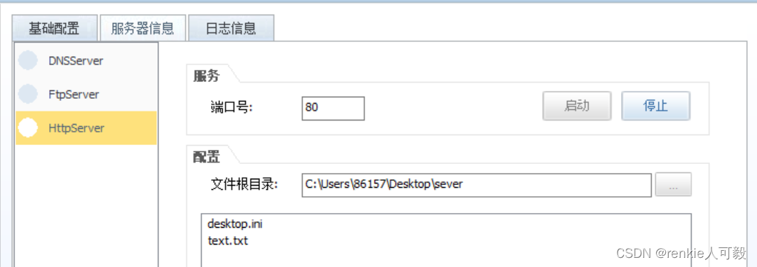
配置FTP服务器
模拟通过DNS解析访问web服务器
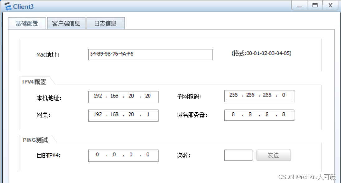
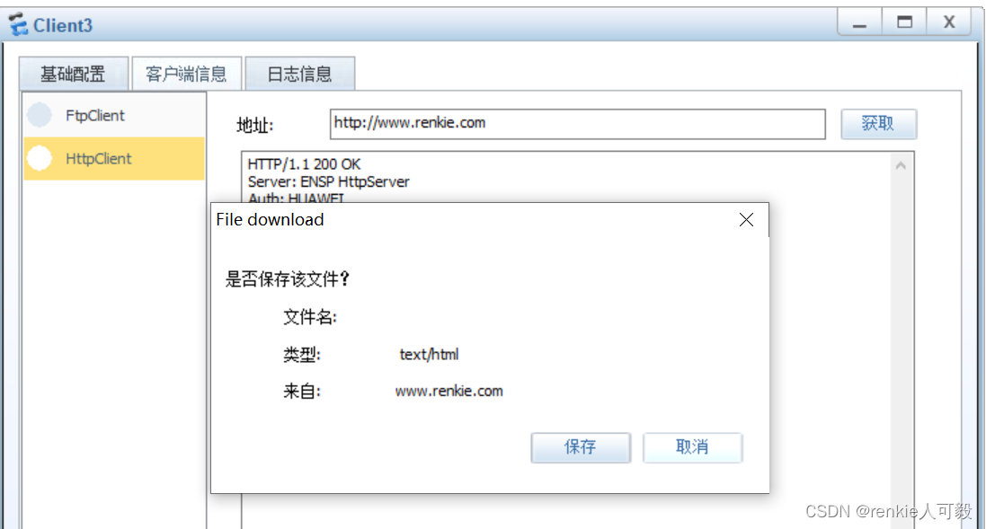
Client3访问WEb服务器
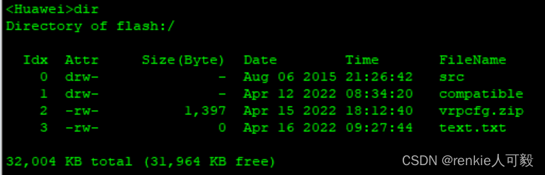
模拟FTP客户端下载文件
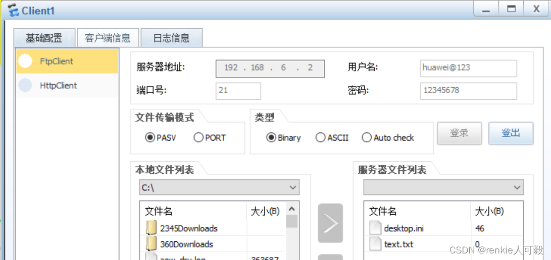
当交换机作为ftp客户端时
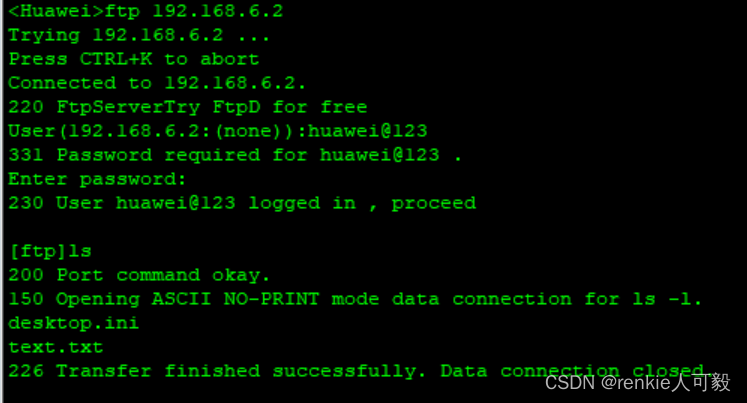 下载text.txt文件
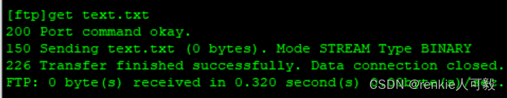
文件下载成功
13.NAT DNS-Map
在某些应用中,私网用户希望通过域名访问位于同一私网的内部服务器,而DNS服务器却位于公网。由于通常DNS响应报文中携带的是内部服务器的公网IP地址,因此若NAT设备未将DNS Server解析的公网IP替换成内部服务器对应的私网IP,私网用户将无法通过域名访问到内部服务器。这个问题可以使用DNS Mapping方式来解决,通过配置“域名—公网IP地址—公网端口—协议类型”映射表,建立内部服务器的域名与其公网信息间的对应关系。
当R1设备收到DNS响应报文后,先根据其中携带的域名查找DNS Mapping映射表,再根据“公网IP地址—公网端口—协议类型”查找Web Server,然后将DNS响应报文中的公网IP地址替换成Web Server的私网IP地址。
以R1配置为例:
nat dns-map www.renkie.com 100.0.1.2 80 tcp
nat alg dns enable   #配置了DNS Mapping后必须执行nat alg dns enable命令使能ALG DNS功能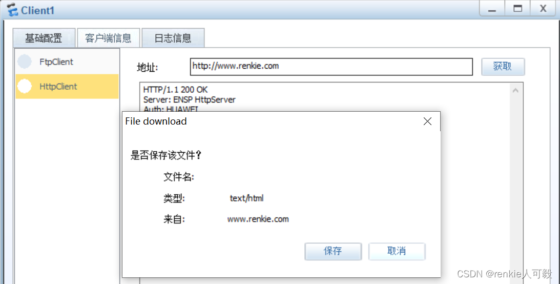
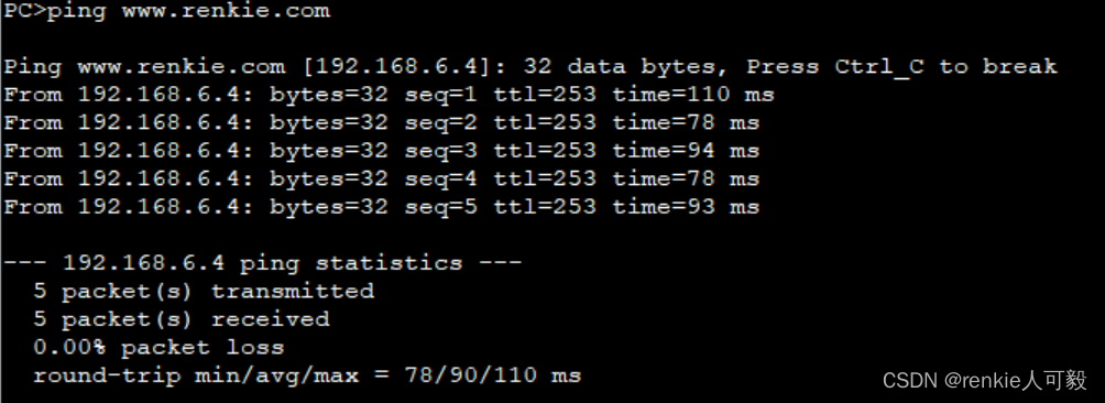
此时ping www.renkie.com,地址也被转换成私网地址了。
14.部门网络权限配置
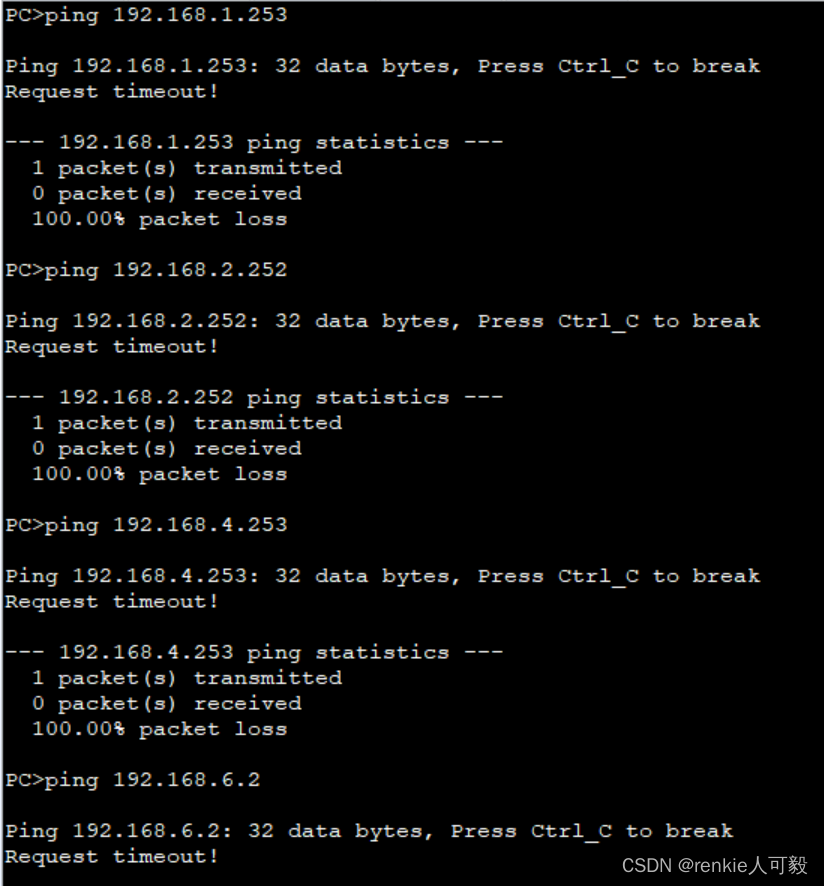
其他部门不能访问财务部,财务部不能访问服务器区域的FTP服务器,财务部不能访问外网,以LSW3配置为例:。
ACL 3000
 rule 1 deny ip source 192.168.3.0 0.0.0.255 destination 192.168.1.0 0.0.0.255
 rule 5 deny ip source 192.168.3.0 0.0.0.255 destination 192.168.2.0 0.0.0.255
 rule 10 deny ip source 192.168.3.0 0.0.0.255 destination 192.168.4.0 0.0.0.255
 rule 15 deny ip source 192.168.3.0 0.0.0.255 destination 192.168.6.2 0.0.0.0
traffic-filter vlan 30 inbound acl 3000
PC3的测试结果如下:
财务部不能访问外网,可以在nat转换时,过滤掉财务部门流量。
acl number 2000
 rule 1 deny source 192.168.3.0 0.0.0.255
PC3测试结果如下:
访客区域只能访问公司web服务器以及外网。
acl 3001
 rule 1 permit ip source 192.168.4.0 0.0.0.255 destination 192.168.6.4 0.0.0.0
 rule 5 permit ip source 192.168.4.0 0.0.0.255 destination 192.168.6.3 0.0.0.0
 rule 10 deny ip source 192.168.4.0 0.0.0.255 destination 192.168.0.0 0.0.255.255
traffic-filter vlan 40 inbound acl 3001
STA的测试结果如下:
技术部与销售部可以互访,且能访问财务部。
acl 3002
 rule 5 permit ip source 192.168.2.0 0.0.0.255 destination 192.168.6.2 0
 rule 10 deny ip destination 192.168.6.2 0
在PC2上测试结果如下:
销售部可以与技术部互访,但不能访问FTP服务器
acl 3003
rule 5 permit ip source 192.168.1.0 0.0.0.255 destination 192.168.2.0 0.0.0.255
rule 10 permit ip source 192.168.1.0 0.0.0.255 destination 192.168.3.0 0.0.0.255
rule 15 permit ip source 192.168.1.0 0.0.0.255 destination 192.168.4.0 0.0.0.255
rule 20 deny ip source 192.168.1.0 0.0.0.255 destination 192.168.6.2 0.0.0.0
traffic-filter vlan 10 inbound acl 3003
PC1测试结果如下:
15.配置IPSec VPN
在R2与R7之间建立IPSec VPN隧道
在R2、R1上建立IPSec VPN隧道,首先要保证总部和分公司的公网地址要可达,即100.0.2.0 和100.0.6.0要互通,前面步骤中将他们都宣告进了ISP的网络中,故而是可达的。
分公司只能访问总部的服务器区域
以R1配置为例。
1.创建ACL,用作感兴趣流,匹配总公司和分部互访的流量。
R2:
acl number 3000
 rule 5 permit ip source 192.168.6.0 0.0.0.255 destination 192.168.20.0 0.0.0.255
*******************************************************************************************
R7:
acl number 3000
rule 15 permit ip source 192.168.20.0 0.0.0.255 destination 192.168.6.0 0.0.0.255 2.配置安全提议
R2:
ipsec proposal huawei
 esp authentication-algorithm sha1 #设置加密方式,默认为MD5
*******************************************************************************************
R7:
ipsec proposal huawei
esp authentication-algorithm sha13.配置ipsec安全策略,策略名为huawei,编号为10,模式为手动配置模式。
R2:
ipsec policy huawei 10 manual
 security acl 3000                         #匹配感兴趣流
 proposal huawei                           #应用名为huawei的提议
 tunnel local 100.0.2.2                    #本地隧道地址
 tunnel remote 100.0.6.254                 #对端隧道地址
 sa spi inbound esp 54321                  #安全联盟入方向,SPI为54321和对端出方向SPI一致
 sa string-key inbound esp cipher huawei   #安全联盟密钥,入方向为加密的huawei,本段入和对端出一致
 sa spi outbound esp 12345                 #安全联盟出方向,SPI为54321和对端入方向SPI一致
 sa string-key outbound esp cipher huawei  #安全联盟密钥,出方向为加密的huawei,本段出和对端入一致
*****************************************************************************************
R7:
ipsec policy huawei 10 manual
 security acl 3000
 proposal huawei
 tunnel local 100.0.6.254
 tunnel remote 100.0.2.2
 sa spi inbound esp 12345
 sa string-key inbound esp cipher huawei
 sa spi outbound esp 54321
 sa string-key outbound esp cipher huawei
#
4.在R2、R7端口应用ipsec policy
R2:
interface GigabitEthernet0/0/2
ipsec policy huawei
*******************************************************************************************
R7:
interface Dialer 1
ipsec policy huawei
在PC5上访问总部服务器区域,如FTP服务器。
抓包来看,只能看见隧道两端的公网地址,私网地址被ipsec封装了

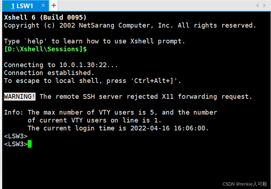
16.通过SSH远程管理设备
路由器采用loopback0作为管理ip地址。交换机采用vlan 1作为管理ip地址。
以LSW1为例,创建管理vlan:
interface Vlanif1
 ip address 10.0.1.10 255.255.255.0
ip route-static 0.0.0.0 0.0.0.0 10.0.1.40 #LSW3的vlan1地址
ip route-static 0.0.0.0 0.0.0.0 10.0.1.30 #LSW4的vlan1地址
配置SSH协议:
stelnet server enable
ssh authentication-type default password
user-inter vty 0 4
au aaa
protocol inbound ssh
aaa
 local-user python password cipher %NS[+B0ZNI]NZPO3JBXBHA!!
 local-user python privilege level 15
 local-user python service-type ssh
验证
将自己的主机桥接到ensp的交换机上 。
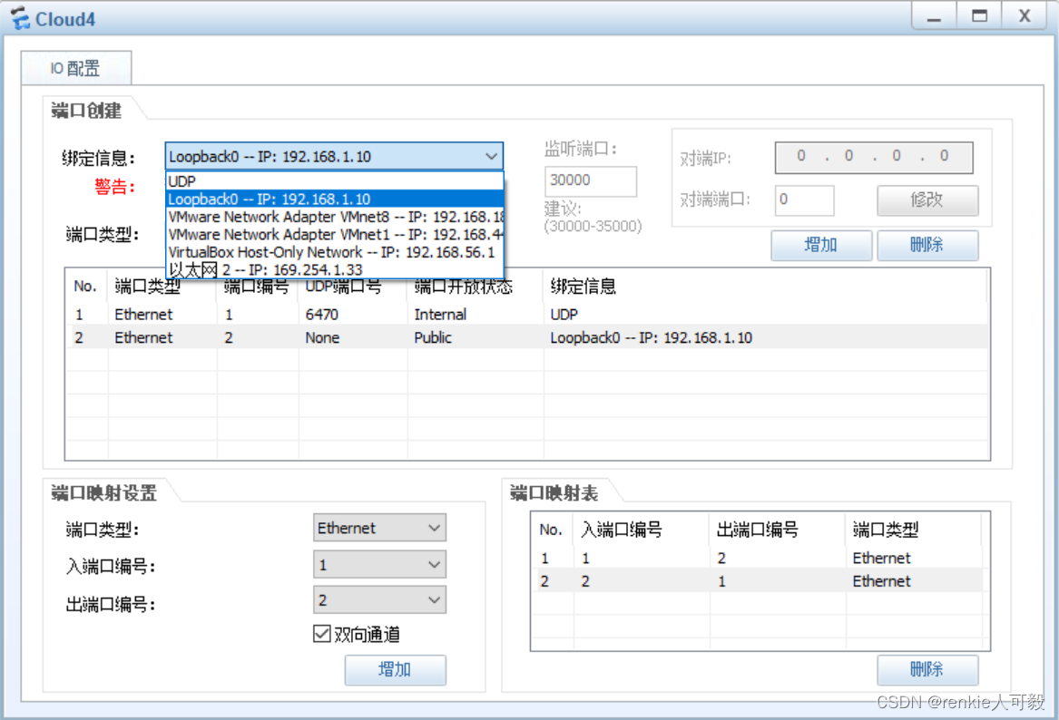
在自己主机创建虚拟网卡loopback0的方法,请自行百度。
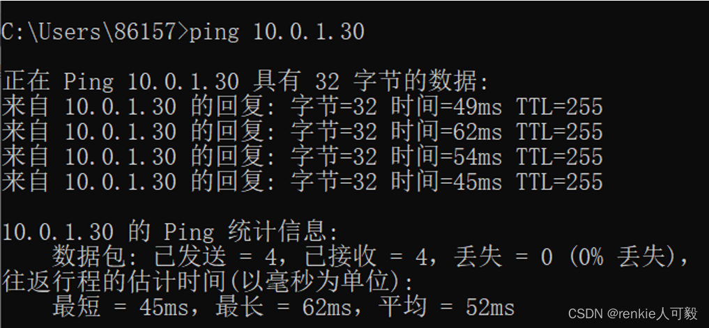
打开cmd,ping LSW3的管理ip地址10.0.1.30,能够ping通,注意要断开自己的网络,不然ping不通。有时ping不通,等待一小段时间就好了,可能网络信息还没变更。
打开xshell,新建一个会话,用来连接LSW3。
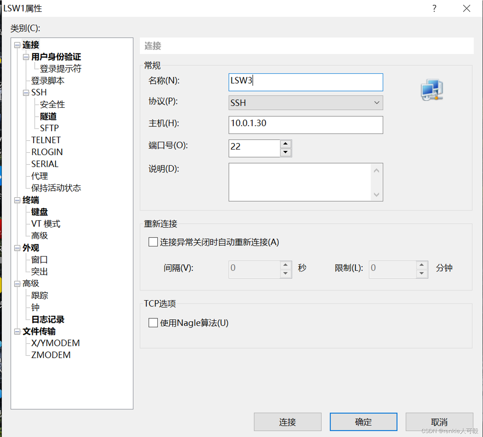
点击连接
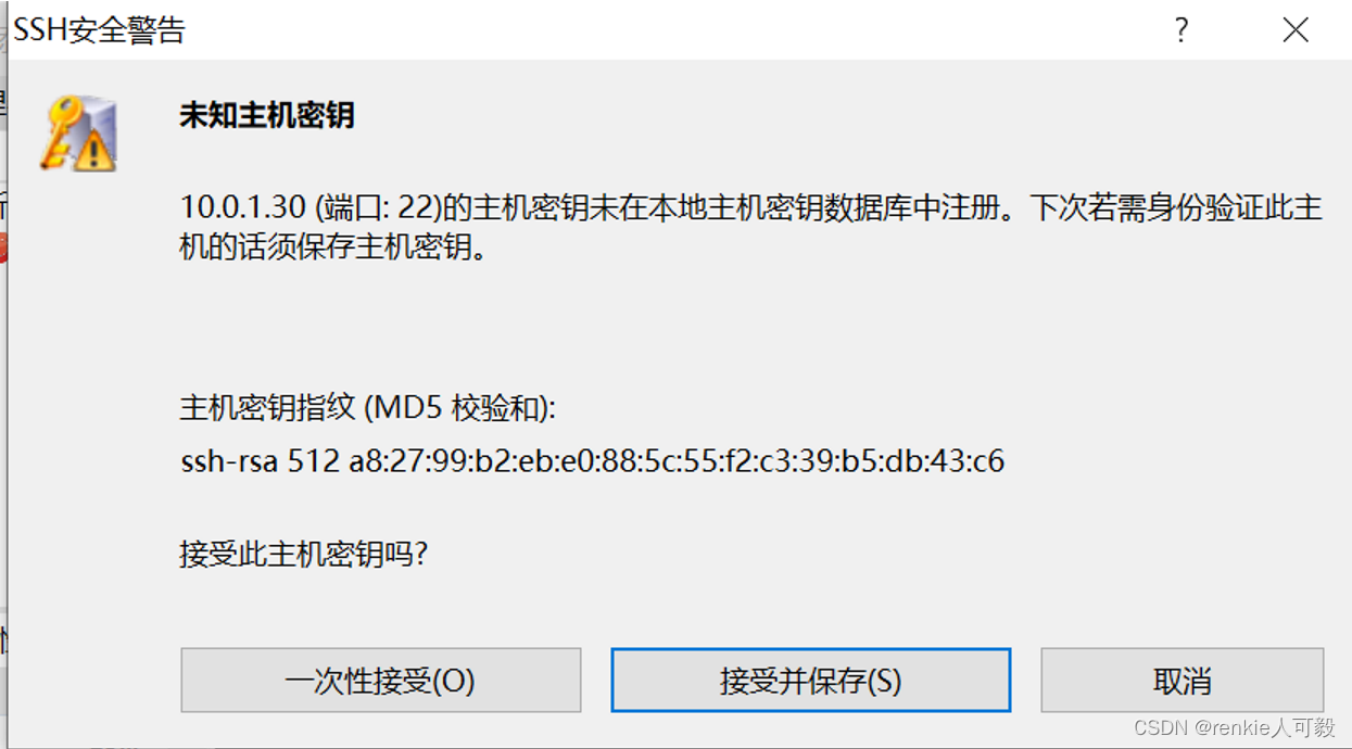 点击接收并保存,输入配置的用户名:huawie,密码:huawei@123
l

为开发者提供学习成长、分享交流、生态实践、资源工具等服务,帮助开发者快速成长。
更多推荐


 89
89 4
4- 0


 已为社区贡献1条内容

所有评论(0)