python双目视觉标定及三维重建
python双目标定及重建写在前面的话: 一个机器视觉的课程作业,是自行采集一组双目图像,完成立体视觉相关流程:包括相机标定(内参和外参)、畸变校正、基本矩阵估算、视差图计算(需要先进行图像矫正)、恢复并画出3D点坐标。网上的代码基本上都是基于棋盘格的,初始不懂,当你抄多了,自然就懂了。原理不多做详细介绍,简单介绍一下实现过程以及遇到的问题,还有最后一部分的重建不能确保准确,因为重建出来的图像单纯
python双目标定及重建
写在前面的话: 一个机器视觉的课程作业,是自行采集一组双目图像,完成立体视觉相关流程:包括相机标定(内参和外参)、畸变校正、基本矩阵估算、视差图计算(需要先进行图像矫正)、恢复并画出3D点坐标。网上的代码基本上都是基于棋盘格的,初始不懂,当你抄多了,自然就懂了。原理不多做详细介绍,简单介绍一下实现过程以及遇到的问题,还有最后一部分的重建不能确保准确,因为重建出来的图像单纯的不好看!文中的代码引用的都已在参考链接里标注,部分进行了更改和补充。
仅供学习使用!
1. 采集图像及预实验
1.1 图像
采集一组双目图像,该步骤由师兄本色出镜,本人用两个手机固定位置同时拍摄,以此得到10对图像。也就是左右手机对在一起,然后同时按快门,该操作定有不小误差。

1.2 matlab 预实验
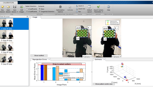
初始使用 cv2.findChessboardCorners 并未检测到任何角点,而且检测时间漫长。因此先使用matlab的工具箱进行预实验(可参考链接3)。得到如下结果,说明数据还是可以被检测出来的。图中的数据已经经过筛选,去除了误差较大的几幅图像。观察其结果并查资料得知,该函数只能检测内角点,因此我的图像给的棋盘大小应为 (7,5) ,因此注意更改参数。

1.3 python 预实验
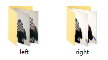
读取 left 和 right 两个文件夹内的所有图像,对其进行角点检测,记录下来能够检测到的图像,并获取能对应起来的图像对,最终可以得到4对图像(10对中才能获取4对,幸好师兄爱上镜)。下面代码中 truth 查看的是能够检测到角点的文件名。
all_images = glob('./datas/*/*.jpg')

truth = []
def test1(image):
    img_l = cv2.imread(image)
    gray_l = cv2.cvtColor(img_l, cv2.COLOR_BGR2GRAY)
    ret_l, corners_l = cv2.findChessboardCorners(gray_l, (7, 5), None)
    if ret_l:
        truth.append(image)

for i in all_images:
    print(f'-------------processing {i}--------------')
    test1(i)
print(truth)
2. 相机标定与参数求解
2.1 确定坐标系以及坐标
- 定义世界坐标系,即三维坐标
- 对左右相机的两幅图像进行角点检测并记录其坐标
- 进行相机标定
关于其原理简单来说就是世界坐标系、相机坐标系、图像坐标系的相互转化,转换之间就是用矩阵进行求解,如何求解就是通过一些计算方式,如通过对应点使用SVD等方式求解。
标定的过程分为两部分:一是从世界坐标系转换为相机坐标系,二是从相机坐标系转为图像坐标系(可参考链接7)。如果知道相机坐标系中的一个点X(现实三维世界中的点),在像平面坐标系对应的点是X’,要求从相机坐标系转为像平面坐标系的转换,可以由一个变换矩阵得到,这个就是相机的内参和偏移量。从世界坐标系转换到相机坐标系是三维空间到三维空间的变换,一般来说需要一个平移操作和一个旋转操作就可以完成这个转换。
畸变(distortion)是对直线投影(rectilinear projection)的一种偏移。简单来说直线投影是场景内的一条直线投影到图片上也保持为一条直线。畸变一般可以分为两大类,包括径向畸变和切向畸变。对于畸变校正,我们可以采用两个相机坐标系的而求得的变换矩阵来进行校正。
通过该步骤我们可以得到二维相机坐标系下的坐标以及距离,包括两个相机内参,基本矩阵,旋转平移矩阵。
求得参数结果如下:
M1: 第一个摄像机的相机矩阵d1: 第一个摄像机的畸变向量M2: 第二个摄像机的相机矩阵d2: 第二个摄像机的畸变向量R: 第一和第二个摄像机之间的旋转矩阵T: 平移矩阵E, F: 基本矩阵
2.2 求解参数
- 通过步骤2.1中得到的参数,计算得到两个相机的内参、畸变向量和基本矩阵,两个相机间的旋转矩阵与平移矩阵
- 通过上一步求得的参数可以求得两个相机的校正变换矩阵,在新坐标系下的投影矩阵,以及深度差异映射矩阵
在使用 remap 重构后,可能得到的图像是黑色的,这是因为双目校正函数 stereoRectify 中的参数 alpha 对矩阵的结果有影响,需要经过调试得到较高质量的重构图像。
求得参数结果如下:
R1: 第一个摄像机的校正变换矩阵(旋转矩阵)R2: 第二个摄像机的校正变换矩阵(旋转矩阵)P1: 第一个摄像机在新坐标系下的投影矩阵P2: 第二个摄像机在新坐标系下的投影矩阵Q: 深度差异映射矩阵
3. 视差图计算
这部分直接借用了 链接3. 中的代码,讲解也比较清楚易懂。简单来说就是经过步骤2.2可以得到相机A与相机B之间相互转换的矩阵,以及投影到二维平面(新坐标系)的投影矩阵,通过矩阵乘法即可得到新的坐标,进行像素赋值即可。函数: cv2.remap
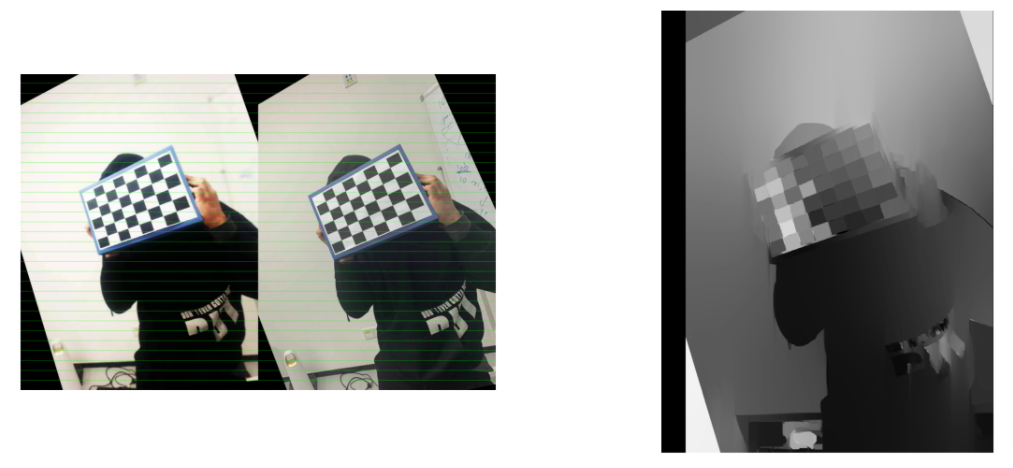
得到的视差图可能是白色一片(投影特别浅),需要调节参数,我将其 sigma 调大了。
# 视差图计算
def depth_map(imgL, imgR, sigma=1.3):
    """ Depth map calculation. Works with SGBM and WLS. Need rectified images, returns depth map ( left to right disparity ) """
    # SGBM Parameters -----------------
    window_size = 3  # wsize default 3; 5; 7 for SGBM reduced size image; 15 for SGBM full size image (1300px and above); 5 Works nicely

    left_matcher = cv2.StereoSGBM_create(
        minDisparity=-1,
        numDisparities=5*16,  # max_disp has to be dividable by 16 f. E. HH 192, 256
        blockSize=window_size,
        P1=8 * 3 * window_size,
        # wsize default 3; 5; 7 for SGBM reduced size image; 15 for SGBM full size image (1300px and above); 5 Works nicely
        P2=32 * 3 * window_size,
        disp12MaxDiff=12,
        uniquenessRatio=10,
        speckleWindowSize=50,
        speckleRange=32,
        preFilterCap=63,
        mode=cv2.STEREO_SGBM_MODE_SGBM_3WAY
    )
    right_matcher = cv2.ximgproc.createRightMatcher(left_matcher)
    # FILTER Parameters
    lmbda = 80000
    visual_multiplier = 6

    wls_filter = cv2.ximgproc.createDisparityWLSFilter(matcher_left=left_matcher)
    wls_filter.setLambda(lmbda)

    wls_filter.setSigmaColor(sigma)
    displ = left_matcher.compute(imgL, imgR)  # .astype(np.float32)/16
    dispr = right_matcher.compute(imgR, imgL)  # .astype(np.float32)/16
    displ = np.int16(displ)
    dispr = np.int16(dispr)
    filteredImg = wls_filter.filter(displ, imgL, None, dispr)  # important to put "imgL" here!!!

    filteredImg = cv2.normalize(src=filteredImg, dst=filteredImg, beta=0, alpha=255, norm_type=cv2.NORM_MINMAX);
    filteredImg = np.uint8(filteredImg)

    return filteredImg
将校对后每对图像合并,并画线查看其结果,与视差图一并显示。其中右图是视差图,仅截屏了一副图像,代码是将其都显示。

4. 重构三维点
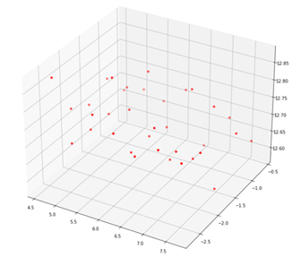
该部分采用了 cv2.triangulatePoints 函数,triangulatePoints 函数得到3d点时,它们处于齐次坐标, points 是 [ x , y , z , w ] [x, y, z, w] [x,y,z,w], w w w 代表齐次的比值,其结果应为 [ x / w , y / w , z / w ] [x/w, y/w, z/w] [x/w,y/w,z/w]

5. 参考链接
- matlab双目标定(详细过程)
- https://github.com/bvnayak/stereo_calibration (在该代码的基础上做了部分更改以及补充)
- 双目立体视觉 I:标定和校正 (代码借鉴较多的部分,值得学习)
- Python计算机视觉-张氏相机内参标定
- 【Python计算机视觉编程】第五章 多视几何
- 还有课程的PPT
- 相机标定(Camera calibration)(原理学习较多的部分)
6. CODE
直接放入计算过程的代码
- 基本函数
import os
import cv2
import numpy as np
from glob import glob
import matplotlib.pyplot as plt

class StereoCalibration():
    def __init__(self, filepath):

        self.criteria = (cv2.TERM_CRITERIA_EPS + cv2.TERM_CRITERIA_MAX_ITER, 30, 0.001)

        # prepare object points, like (0,0,0), (1,0,0), (2,0,0) ....,(6,5,0)
        self.objp = np.zeros((7*5, 3), np.float32)
        self.objp[:, :2] = np.mgrid[0:7, 0:5].T.reshape(-1, 2)

        # Arrays to store object points and image points from all the images.
        self.objpoints = []  # 3d point in real world space
        self.imgpoints_l = []  # 2d points in image plane.
        self.imgpoints_r = []  # 2d points in image plane.

        self.filepath = filepath
        self.read_images()

    def read_images(self):
        images_right = glob(self.filepath + 'right/[4|6|8].jpg') + ['./datas/right/11.jpg']
        images_left = glob(self.filepath + 'left/[4|6|8].jpg') + ['./datas/left/11.jpg']

        for i, fname in enumerate(images_right):
            img_l = cv2.imread(images_left[i])
            img_r = cv2.imread(images_right[i])

            gray_l = cv2.cvtColor(img_l, cv2.COLOR_BGR2GRAY)
            gray_r = cv2.cvtColor(img_r, cv2.COLOR_BGR2GRAY)

            # Find the chess board corners
            ret_l, corners_l = cv2.findChessboardCorners(gray_l, (7, 5), None)
            ret_r, corners_r = cv2.findChessboardCorners(gray_r, (7, 5), None)

            # If found, add object points, image points (after refining them)


            if ret_l and ret_r:

                self.objpoints.append(self.objp)

                rt = cv2.cornerSubPix(gray_l, corners_l, (5, 5), (-1, -1), self.criteria)
                self.imgpoints_l.append(corners_l)

                rt = cv2.cornerSubPix(gray_r, corners_r, (5, 5), (-1, -1), self.criteria)
                self.imgpoints_r.append(corners_r)
            else:
                print('Couldn\'t be found')

            img_shape = gray_l.shape[::-1]

        rt, self.M1, self.d1, self.r1, self.t1 = cv2.calibrateCamera(self.objpoints, self.imgpoints_l, img_shape, None, None)
        rt, self.M2, self.d2, self.r2, self.t2 = cv2.calibrateCamera(self.objpoints, self.imgpoints_r, img_shape, None, None)

        self.camera_model = self.stereo_calibrate(img_shape)

    def stereo_calibrate(self, dims):

        h, w = dims

        flags = 0
        # 如果该标志被设置,那么就会固定输入的cameraMatrix和distCoeffs不变,只求解R,T,E,F.
        flags |= cv2.CALIB_FIX_INTRINSIC
        # 根据用户提供的cameraMatrix和distCoeffs为初始值开始迭代
        flags |= cv2.CALIB_USE_INTRINSIC_GUESS
        # 迭代过程中不会改变焦距
        flags |= cv2.CALIB_FIX_FOCAL_LENGTH
        # 切向畸变保持为零
        flags |= cv2.CALIB_ZERO_TANGENT_DIST


        stereocalib_criteria = (cv2.TERM_CRITERIA_MAX_ITER + cv2.TERM_CRITERIA_EPS, 100, 1e-5)
        ret, M1, d1, M2, d2, R, T, E, F = cv2.stereoCalibrate(
            self.objpoints,
            self.imgpoints_l,
            self.imgpoints_r,
            self.M1,
            self.d1,
            self.M2,
            self.d2,
            dims,
            criteria=stereocalib_criteria,
            flags=flags
        )

        camera_model = dict([
            ('M1', M1),
            ('M2', M2),
            ('dist1', d1),
            ('dist2', d2),
            ('rvecs1', self.r1),
            ('rvecs2', self.r2),
            ('R', R),
            ('T', T),
            ('E', E),
            ('F', F),
            ('dim', (h, w))
        ])

        return camera_model

    def rectify(self, camera_model):

        M1, d1, M2, d2, R, T =  camera_model.get('M1'), camera_model.get('d1'), camera_model.get('M2'), camera_model.get('d2'), camera_model.get('R'), camera_model.get('T')

        # 双目矫正 alpha=-1, 0, 0.9
        R1, R2, P1, P2, Q, validPixROI1, validPixROI2 = cv2.stereoRectify(M1, d1, M2, d2, camera_model.get('dim'), R, T, alpha=-1)
        print('stereo rectify done...')

        # 得到映射变换
        stereo_left_mapx, stereo_left_mapy = cv2.initUndistortRectifyMap(M1, d1, R1, P1, camera_model.get('dim'), cv2.CV_32FC1)
        stereo_right_mapx, stereo_right_mapy = cv2.initUndistortRectifyMap(M2, d2, R2, P2, camera_model.get('dim'), cv2.CV_32FC1)
        print('initUndistortRectifyMap done...')

        rectify_model = dict([
            ('R1', R1),
            ('R2', R2),
            ('P1', P1),
            ('P2', P2),
            ('Q', Q),
            ('stereo_left_mapx', stereo_left_mapx),
            ('stereo_left_mapy', stereo_left_mapy),
            ('stereo_right_mapx', stereo_right_mapx),
            ('stereo_right_mapy', stereo_right_mapy)
        ])

        return rectify_model

# 视差图计算
# 略,复制第3部分

# 画线函数
def drawLine(img, num=16):
    h, w, _ = img.shape
    for i in range(0, h, h // num):
        cv2.line(img, (0, i), (w, i), (0, 255, 0), 1, 8)
    return img
- 创建对象,得到基本参数
filepath = 'X:/Notebook/HW/CV/datas/'
cal_data = StereoCalibration(filepath)
# 得到相机参数
camera_model = cal_data.camera_model
# 得到修正参数
rectify_model = cal_data.rectify(camera_model)
- 可视化结果
stereo_left_mapx, stereo_left_mapy = rectify_model.get('stereo_left_mapx'), rectify_model.get('stereo_left_mapy')
stereo_right_mapx, stereo_right_mapy = rectify_model.get('stereo_right_mapx'), rectify_model.get('stereo_right_mapy')

# 看网格是否对齐, 并且显示视差图
plt.figure(figsize=(20,40))
num = 1
for i in range(len(left_images)):
    left_img = cv2.imread(left_images[i])
    right_img = cv2.imread(right_images[i])

    frame0 = cv2.remap(right_img, stereo_right_mapx, stereo_right_mapy, cv2.INTER_LINEAR, cv2.BORDER_CONSTANT)
    frame1 = cv2.remap(left_img, stereo_left_mapx, stereo_left_mapy, cv2.INTER_LINEAR, cv2.BORDER_CONSTANT)
    gray_left = cv2.cvtColor(frame0, cv2.COLOR_BGR2GRAY)
    gray_right = cv2.cvtColor(frame1, cv2.COLOR_BGR2GRAY)
    img = np.concatenate((frame0, frame1), axis=1).copy()
    img = drawLine(img, 32)
    plt.subplot(len(left_images), 2, num)
    plt.axis('off')
    plt.imshow(img[...,::-1])
    num += 1

    disparity_image = depth_map(gray_left, gray_right, sigma=2.0)
    plt.subplot(len(left_images), 2, num)
    plt.axis('off')
    plt.imshow(disparity_image, cmap='gray')
    num += 1
#     break
- 重构
pls = [np.array(i) for i in cal_data.imgpoints_l]
prs = [np.array(i) for i in cal_data.imgpoints_r]

# 取一对图像的二维坐标点
ptl, ptr = pls[0], prs[0]
P1 = rectify_model.get('P1')
P2 = rectify_model.get('P2')

points = cv2.triangulatePoints(P1,P2,ptl,ptr)
coodinates_x = points[0] / points[-1]
coodinates_y = points[1] / points[-1]
coodinates_z = points[2] / points[-1]

# 转换成三维坐标的形式,直接reshape结果不对
coodinates = np.array([[i,j,k] for i,j,k in zip(coodinates_x, coodinates_y, coodinates_z)])

fig = plt.figure(figsize=(12,12))
ax = fig.add_subplot(111, projection='3d')

plt.cla()
coodinates_x, coodinates_y, coodinates_z
ax.scatter(coodinates[:, 0], coodinates[:, 1], coodinates[:, 2], color='red')
plt.draw()
plt.show()
更多推荐
 已为社区贡献1条内容


所有评论(0)