
树莓派从零开始快速入门第11讲——SPI(以OLED为例)
SPI是外设驱动常用的通讯方式之一,相比于IIC,SPI数据传输的速率要更高,因为SPI比IIC多了一根数据线,是全双工的。具体的通讯原理这里就不多介绍了,我主要讲解树莓派的SPI编程部分。因为我的扩展板只有OLED连的是SPI接口,所以这一讲就以OLED为例。
树莓派从零开始快速入门第11讲——SPI(以OLED为例)
一、前言
SPI是外设驱动常用的通讯方式之一,相比于IIC,SPI数据传输的速率要更高,因为SPI比IIC多了一根数据线,是全双工的。具体的通讯原理这里就不多介绍了,我主要讲解树莓派的SPI编程部分。因为我的扩展板只有OLED连的是SPI接口,所以这一讲就以OLED为例。
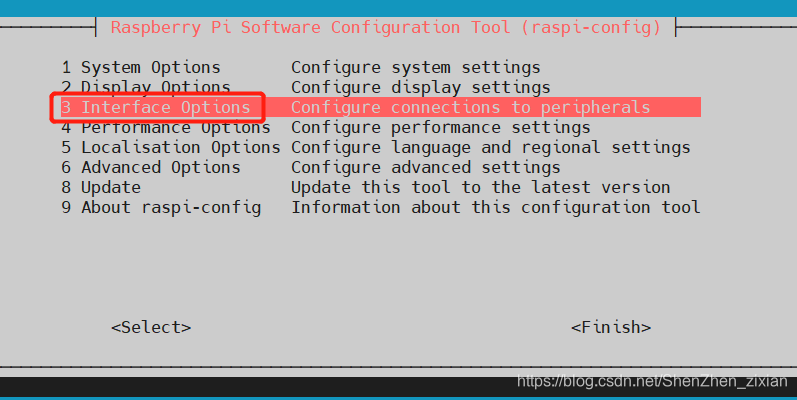
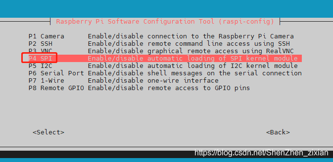
二、使能树莓派SPI接口
方法1:通过配置命令
sudo raspi-config // 打开配置
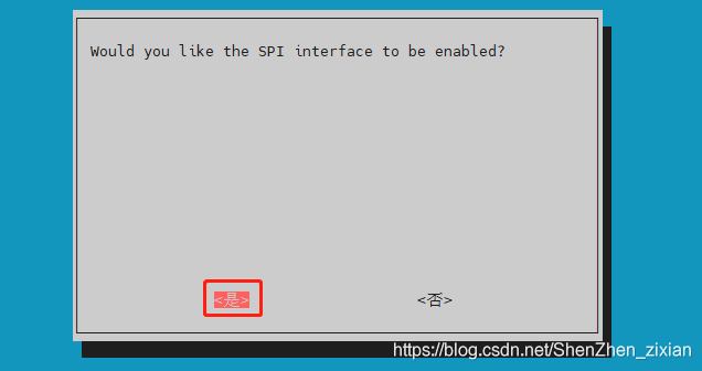
sudo reboot // 重启,如果之前没有使能,配置完之后要重启才能生效
方法2:在可视化界面的设置里面修改
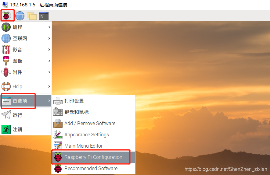
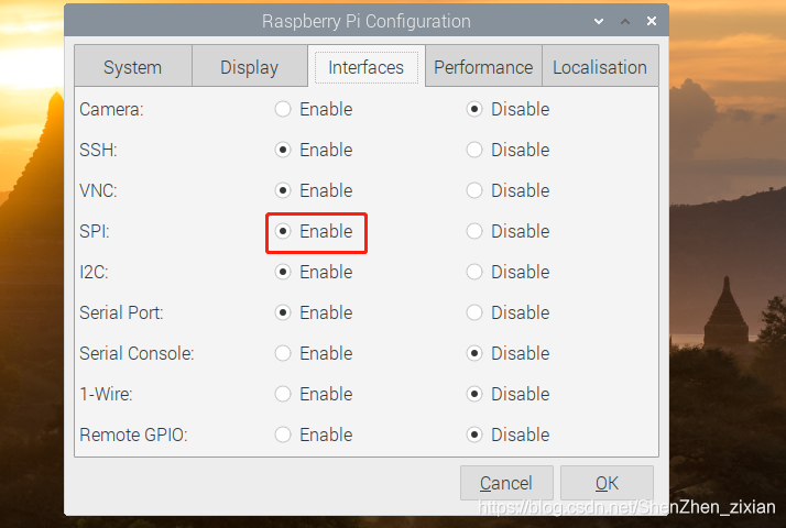
如果之前没有使能,配置完之后要重启才能生效
三、编写程序及运行
SPI通讯主要用的是spidev库,该库的api可以参考下面这个链接。
spidev库:https://pypi.org/project/spidev
图像文字显示主要用的是python图像处理PIL库,关于这个库的详细情况可以参考下面这篇博文。
https://blog.csdn.net/zhangziju/article/details/79123275
代码主要分成两部分:驱动部分和应用部分
驱动部分是通过spi和SSD1306芯片通信,实现显示数据的传输。
应用部分就是根据你的需求,在对应的位置显示你想要的内容。
驱动部分代码如下:
SSD1306.py
import spidev
import RPi.GPIO as GPIO
import time

# Constants
SSD1306_SETCONTRAST = 0x81
SSD1306_DISPLAYALLON_RESUME = 0xA4
SSD1306_DISPLAYALLON = 0xA5
SSD1306_NORMALDISPLAY = 0xA6
SSD1306_INVERTDISPLAY = 0xA7
SSD1306_DISPLAYOFF = 0xAE
SSD1306_DISPLAYON = 0xAF
SSD1306_SETDISPLAYOFFSET = 0xD3
SSD1306_SETCOMPINS = 0xDA
SSD1306_SETVCOMDETECT = 0xDB
SSD1306_SETDISPLAYCLOCKDIV = 0xD5
SSD1306_SETPRECHARGE = 0xD9
SSD1306_SETMULTIPLEX = 0xA8
SSD1306_SETLOWCOLUMN = 0x00
SSD1306_SETHIGHCOLUMN = 0x10
SSD1306_SETSTARTLINE = 0x40
SSD1306_MEMORYMODE = 0x20
SSD1306_COLUMNADDR = 0x21
SSD1306_PAGEADDR = 0x22
SSD1306_COMSCANINC = 0xC0
SSD1306_COMSCANDEC = 0xC8
SSD1306_SEGREMAP = 0xA0
SSD1306_CHARGEPUMP = 0x8D
SSD1306_EXTERNALVCC = 0x1
SSD1306_SWITCHCAPVCC = 0x2

# Scrolling constants
SSD1306_ACTIVATE_SCROLL = 0x2F
SSD1306_DEACTIVATE_SCROLL = 0x2E
SSD1306_SET_VERTICAL_SCROLL_AREA = 0xA3
SSD1306_RIGHT_HORIZONTAL_SCROLL = 0x26
SSD1306_LEFT_HORIZONTAL_SCROLL = 0x27
SSD1306_VERTICAL_AND_RIGHT_HORIZONTAL_SCROLL = 0x29
SSD1306_VERTICAL_AND_LEFT_HORIZONTAL_SCROLL = 0x2A


class SSD1306(object):
    """class for SSD1306  128*64 0.96inch OLED displays."""

    def __init__(self, rst, dc, spi):
        self.width = 128
        self.height = 64
        self._pages = 8
        self._buffer = [0]*(self.width*self._pages)
        # Initialize DC RST pin
        self._dc = dc
        self._rst = rst
        GPIO.setmode(GPIO.BCM)
        GPIO.setwarnings(False)
        GPIO.setup(self._dc, GPIO.OUT)
        GPIO.setup(self._rst, GPIO.OUT)
        # Initialize SPI
        self._spi = spi

    def command(self, cmd):
        """Send command byte to display"""
        GPIO.output(self._dc, GPIO.LOW)
        self._spi.writebytes([cmd])

    def data(self, val):
        """Send byte of data to display"""
        GPIO.output(self._dc, GPIO.HIGHT)
        self._spi.writebytes([val])

    def begin(self, vccstate=SSD1306_SWITCHCAPVCC):
        """Initialize dispaly"""
        self._vccstate = vccstate
        self.reset()
        self.command(SSD1306_DISPLAYOFF)                    # 0xAE
        self.command(SSD1306_SETDISPLAYCLOCKDIV)            # 0xD5
        self.command(0x80)                     # the suggested ra    tio 0x80

        self.command(SSD1306_SETMULTIPLEX)                  # 0xA8
        self.command(0x3F)
        self.command(SSD1306_SETDISPLAYOFFSET)              # 0xD3
        self.command(0x0)                                   # no offset
        self.command(SSD1306_SETSTARTLINE | 0x0)            # line #0
        self.command(SSD1306_CHARGEPUMP)                    # 0x8D
        if self._vccstate == SSD1306_EXTERNALVCC:
            self.command(0x10)
        else:
            self.command(0x14)
        self.command(SSD1306_MEMORYMODE)                    # 0x20
        self.command(0x00)                            # 0x0 act like ks0108
        self.command(SSD1306_SEGREMAP | 0x1)
        self.command(SSD1306_COMSCANDEC)
        self.command(SSD1306_SETCOMPINS)                    # 0xDA
        self.command(0x12)
        self.command(SSD1306_SETCONTRAST)                   # 0x81
        if self._vccstate == SSD1306_EXTERNALVCC:
            self.command(0x9F)
        else:
            self.command(0xCF)
        self.command(SSD1306_SETPRECHARGE)                  # 0xd9
        if self._vccstate == SSD1306_EXTERNALVCC:
            self.command(0x22)
        else:
            self.command(0xF1)
        self.command(SSD1306_SETVCOMDETECT)                 # 0xDB
        self.command(0x40)
        self.command(SSD1306_DISPLAYALLON_RESUME)           # 0xA4
        self.command(SSD1306_NORMALDISPLAY)                 # 0xA6
        self.command(SSD1306_DISPLAYON)

    def reset(self):
        """Reset the display"""
        GPIO.output(self._rst, GPIO.HIGH)
        time.sleep(0.001)
        GPIO.output(self._rst, GPIO.LOW)
        time.sleep(0.010)
        GPIO.output(self._rst, GPIO.HIGH)

    def display(self):
        """Write display buffer to physical display"""
        self.command(SSD1306_COLUMNADDR)
        self.command(0)  # Cloumn start address
        self.command(self.width-1)  # Cloumn end address
        self.command(SSD1306_PAGEADDR)
        self.command(0)  # Page start address
        self.command(self._pages-1)  # Page end address
        # Write buffer data
        GPIO.output(self._dc, GPIO.HIGH)
        self._spi.writebytes(self._buffer)

    def image(self, image):
        """Set buffer to value of Python Imaging Library image."""
        if image.mode != '1':
            raise ValueError('Image must be in mode 1.')
        imwidth, imheight = image.size
        if imwidth != self.width or imheight != self.height:
            raise ValueError('Image must be same dimensions as display \
				({0}x{1}).' .format(self.width, self.height))

        pix = image.load()
        # Iterate through the memory pages
        index = 0
        for page in range(self._pages):
            # Iterate through all x axis columns.
            for x in range(self.width):
                # Set the bits for the column of pixels at the current position.
                bits = 0
                # Don't use range here as it's a bit slow
                for bit in [0, 1, 2, 3, 4, 5, 6, 7]:
                    bits = bits << 1
                    bits |= 0 if pix[(x, page*8+7-bit)] == 0 else 1
                # Update buffer byte and increment to next byte.
                self._buffer[index] = bits
                index += 1

    def clear(self):
        """Clear contents of image buffer"""
        self._buffer = [0]*(self.width*self._pages)

    def set_contrast(self, contrast):
        """Sets the contrast of the display.
        Contrast should be a value between 0 and 255."""
        if contrast < 0 or contrast > 255:
            raise ValueError('Contrast must be a value from 0 to 255).')
        self.command(SSD1306_SETCONTRAST)
        self.command(contrast)

    def dim(self, dim):
        """Adjusts contrast to dim the display if dim is True,
        otherwise sets the contrast to normal brightness if dim is False."""
        # Assume dim display.
        contrast = 0
        # Adjust contrast based on VCC if not dimming.
        if not dim:
            if self._vccstate == SSD1306_EXTERNALVCC:
                contrast = 0x9F
            else:
                contrast = 0xCF
应用部分代码如下:
oled.py
import spidev as SPI
import SSD1306
import time

from PIL import Image,ImageDraw,ImageFont

# Raspberry Pi pin configuration:
RST = 19
DC = 16
bus = 0
device = 0

# 128x64 display with hardware SPI:
disp = SSD1306.SSD1306(RST, DC, SPI.SpiDev(bus, device))

# Initialize library.
disp.begin()

# Clear display.
disp.clear()
disp.display()

# Create blank image for drawing.
# Make sure to create image with mode '1' for 1-bit color.
width = disp.width
height = disp.height
image = Image.new('1', (width, height))

# Get drawing object to draw on image.
draw = ImageDraw.Draw(image)

# Draw a black filled box to clear the image.
draw.rectangle((0,0,width,height), outline=0, fill=0)

# Draw some shapes.
# First define some constants to allow easy resizing of shapes.
padding = 2
shape_width = 20
top = padding
bottom = height-padding
# Move left to right keeping track of the current x position for drawing shapes.
x = padding
# Draw an ellipse.
draw.ellipse((x, top , x+shape_width, bottom), outline=255, fill=0)
x += shape_width+padding
# Draw a rectangle.
draw.rectangle((x, top, x+shape_width, bottom), outline=255, fill=0)
x += shape_width+padding
# Draw a triangle.
draw.polygon([(x, bottom), (x+shape_width/2, top), (x+shape_width, bottom)], outline=255, fill=0)
x += shape_width+padding
# Draw an X.
draw.line((x, bottom, x+shape_width, top), fill=255)
draw.line((x, top, x+shape_width, bottom), fill=255)
x += shape_width+padding

# Load default font.
font = ImageFont.load_default()

# Write two lines of text.
draw.text((x, top),    'Hello',  font=font, fill=255)
draw.text((x, top+20), 'World!', font=font, fill=255)

# Display image.
disp.image(image)
disp.display()
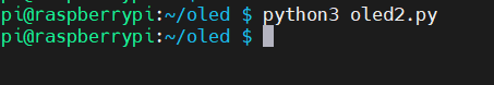
运行结果:
运行oled.py,OLED从左到右分别显示的是一个椭圆形,一个矩形,一个三角形,一个字母“X”,两个字符串Hello world!(摄像头怎么拍都拍不好将就着看吧)

四、进阶学习
1、显示中文
PIL默认的字库是没有中文的,如果我们要显示中文的话要用第三方的库,我这边下载了一个带中文的字库wqy-zenhei.ttf(文泉驿正黑)。
示例代码:
#-*- coding:utf-8 -*-
import spidev as SPI
import SSD1306
import time

# import sys
# reload(sys)
# sys.setdefaultencoding('utf-8')

from PIL import Image,ImageDraw,ImageFont

# Raspberry Pi pin configuration:
RST = 19
DC = 16
bus = 0
device = 0

# 128x64 display with hardware SPI:
disp = SSD1306.SSD1306(RST, DC, SPI.SpiDev(bus, device))

# Initialize library.
disp.begin()

# Clear display.
disp.clear()
disp.display()

# Create blank image for drawing.
# Make sure to create image with mode '1' for 1-bit color.
width = disp.width
height = disp.height
image = Image.new('1', (width, height))

# Get drawing object to draw on image.
draw = ImageDraw.Draw(image)

# Draw a black filled box to clear the image.
draw.rectangle((0,0,width,height), outline=0, fill=0)

# Draw some shapes.
# First define some constants to allow easy resizing of shapes.
padding = 2
shape_width = 20
top = padding
bottom = height-padding
# Move left to right keeping track of the current x position for drawing shapes.
x = padding
# Draw an ellipse.
draw.ellipse((x, top , x+shape_width, bottom), outline=255, fill=0)
x += shape_width+padding
# Draw a rectangle.
draw.rectangle((x, top, x+shape_width, bottom), outline=255, fill=0)
x += shape_width+padding
# Draw a triangle.
draw.polygon([(x, bottom), (x+shape_width/2, top), (x+shape_width, bottom)], outline=255, fill=0)
x += shape_width+padding
# Draw an X.
draw.line((x, bottom, x+shape_width, top), fill=255)
draw.line((x, top, x+shape_width, bottom), fill=255)
x += shape_width+padding

# Load default font.
# font = ImageFont.load_default()
# 使用wqy-zenhei.ttf字库,字号设置为16,字库需要自己下载并放到同一目录下,如果不在同一目录下需要指定路径。字库下载推荐:https://www.dafont.com/bitmap.php
font = ImageFont.truetype('wqy-zenhei.ttf', 16)

# Write two lines of text.
draw.text((x, top),    'Hello',  font=font, fill=255)
draw.text((x, top+20), '你好', font=font, fill=255)
# txt2lcd('星期',x,top+40)

# Display image.
disp.image(image)
disp.display()
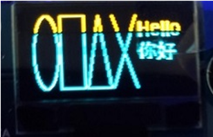
运行结果:
注意:运行该代码要用python3版本,用1和2运行都会报错。还有,python3有一点不同的是,空格和tab是不一样的,如果你前面用的是tab,后面就要全部统一,否则会报错。
2、显示图片
1)首先要准备一张2:1的图片
为什么是2:1呢?因为我用的0.96寸的oled屏是2:1的。
下面这张图我是按2:1裁剪出来的。
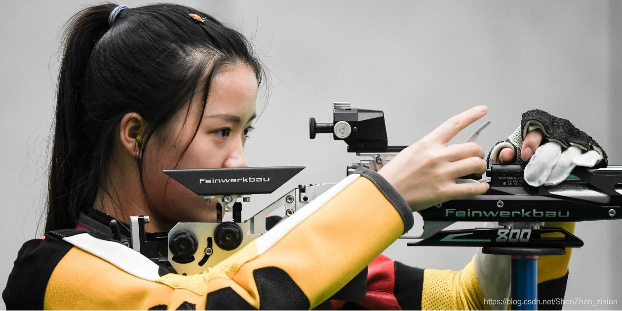
2)编辑图片,把分辨率调节为128*64并另存为单色位图的bmp格式
因为我用的0.96寸的oled屏分辨率就是128*64的,而且每个像素点的颜色都是是固定的

3)编写代码
示例代码1:
# Copyright (c) 2015 WaveShare
# Author: My MX
import time

import spidev as SPI
import SSD1306

# import Image
from PIL import Image

# Raspberry Pi pin configuration:
RST = 19
DC = 16
bus = 0
device = 0


# 128x32 display with hardware I2C:
disp = SSD1306.SSD1306(rst=RST,dc=DC,spi=SPI.SpiDev(bus,device))

# Initialize library.
disp.begin()

# Clear display.
disp.clear()
disp.display()

# Load image based on OLED display height.  Note that image is converted to 1 bit color.
image = Image.open('test.bmp').convert('1') # 加载

# Alternatively load a different format image, resize it, and convert to 1 bit color.
#image = Image.open('happycat.png').resize((disp.width, disp.height), Image.ANTIALIAS).convert('1')

# Display image.
disp.image(image)
disp.display()
4)运行代码
注意:图片的名称和代码写的要一致,要把做好的图片和代码放在同一目录下,如果不在同一目录,需要指明图片的路径。
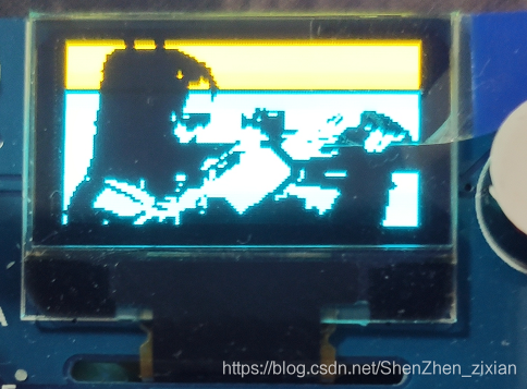
运行结果:
PS:实际效果要好一些,拍出来有色差
示例代码2:
显示一张ppm格式的图片
import time

import spidev as SPI
import SSD1306

from PIL import Image

# Raspberry Pi pin configuration:
RST = 19
DC = 16
bus = 0
device = 0

# 128x32 display with hardware I2C:
disp = SSD1306.SSD1306(rst=RST,dc=DC,spi=SPI.SpiDev(bus,device))

# Initialize library.
disp.begin()

# Clear display.
disp.clear()
disp.display()

# Load image based on OLED display height.  Note that image is converted to 1 bit color.
image = Image.open('happycat.ppm').convert('1')

# Alternatively load a different format image, resize it, and convert to 1 bit color.
#image = Image.open('happycat.png').resize((disp.width, disp.height), Image.ANTIALIAS).convert('1')

# Display image.
disp.image(image)
disp.display()
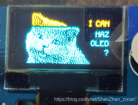
运行结果:
五、结束语
总的来说,在应用层的使用,SPI和IIC差不多,都是直接调用api接口即可,只是用的库函数不一样,并不需要管底层的通讯是怎样实现的。
好了,这一讲的内容就这么多了,如果对你有帮助,可以给个收藏,如果想了解更多树莓派的知识可以关注我,后续我会继续更新更多的教程。
树莓派入门系列教程:树莓派从零开始快速入门系列汇总
教程相关的软件和源码:https://pan.baidu.com/s/1-lVAZyH2s-VTn5qeSnEPhA ,提取码:qwer

为开发者提供学习成长、分享交流、生态实践、资源工具等服务,帮助开发者快速成长。
更多推荐


 12
12 0
0- 0


 已为社区贡献4条内容

所有评论(0)